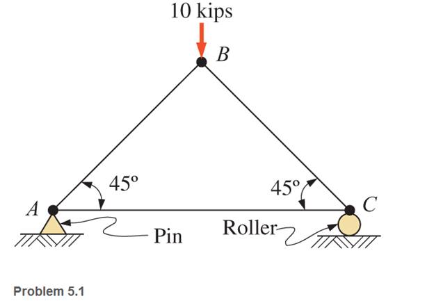
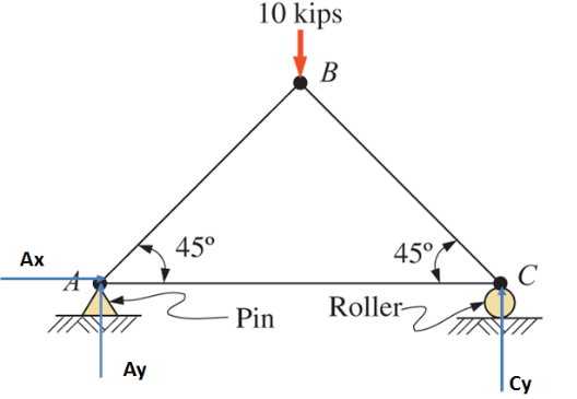
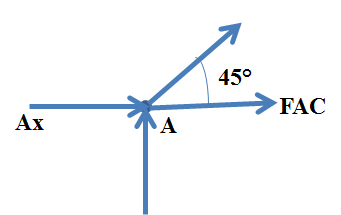
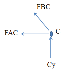
Problem 5.1P: through 5.7 Calculate the forces in all members of the trusses shown, using the method of joints. Problem 5.2P: Calculate the forces in all members of the trusses shown, using the method of joints. Problem 5.3P: Calculate the forces in all members of the trusses shown, using the method of joints. Problem 5.4P: Calculate the forces in all members of the trusses shown, using the method of joints. Problem 5.5P: Calculate the forces in all members of the trusses shown, using the method of joints. Problem 5.6P: Calculate the forces in all members of the trusses shown, using the method of joints. Problem 5.7P: Calculate the forces in all members of the trusses shown, using the method of joints. Problem 5.8P: Determine the forces in members CD, DH, and HI for the truss shown. Problem 5.9P: Determine the forces in members BC, BE, and FE for the truss shown. Problem 5.10P: Determine the forces in members BC, CH, and CG in the truss shown. Problem 5.11P: For the Howe roof truss shown, determine the forces in members BC, CI, and IJ. Problem 5.12P: Determine the forces in members DE, CE, and BC in the truss shown. Problem 5.13P: Calculate the forces in members BC, BG, and FG for the cantilever truss shown. Problem 5.14P: Determine the forces in members CD, BD, BE, and CB in the yoke truss shown. Problem 5.15P: A pin-connected A-frame supports a load, as shown. Compute the pin reactions at all of the pins.... Problem 5.16P: Determine the pin reactions at pins A, B, and C in the frame shown. Neglect the weights of the... Problem 5.17P: Calculate the pin reactions at each of the pins in the frame shown. Problem 5.18P: A bracket is pin connected at points A, B, and D and is subjected to loads, as shown. Calculate the... Problem 5.19P: A pin-connected frame is loaded, as shown. Calculate the pin reactions at A, B, and C. Neglect the... Problem 5.20P: The cylinder shown has a mass of 500 kg. Determine the force in member AB and the pin reaction at C.... Problem 5.21P: A simple frame is pin connected at points A, B, and C and is subjected to loads as shown. Compute... Problem 5.22P: Using the method of sections, determine the forces in CE and ED in the vertical truss of Problem... Problem 5.23P: Using the method of sections, determine the forces in members BD and BE of the truss shown. Problem 5.24SP: through 5.31 Calculate the forces in all members of the trusses shown, using the method of joints. Problem 5.25SP: Calculate the forces in all members of the trusses shown, using the method of joints. Problem 5.26SP: Calculate the forces in all members of the trusses shown, using the method of joints. Problem 5.27SP: Calculate the forces in all members of the trusses shown, using the method of joints. Problem 5.28SP: Calculate the forces in all members of the trusses shown, using the method of joints. Problem 5.29SP: Calculate the forces in all members of the trusses shown, using the method of joints. Problem 5.30SP: Calculate the forces in all members of the trusses shown, using the method of joints. Problem 5.31SP: Calculate the forces in all members of the trusses shown, using the method of joints. Problem 5.32SP: For Problems 5.32 through 5.38, calculate the forces in the indicated members of the trusses shown.... Problem 5.33SP: For Problem 5.32 through 5.38, Calculate the forces in the indicated members of the trusses shown.... Problem 5.34SP: For Problems 5.32 through 5.38, calculate the forces in the indicated members of the trusses shown.... Problem 5.35SP: For Problems 5.32 through 5.38, calculate the forces in the indicated members of the trusses shown.... Problem 5.36SP: For Problem 5.32 through 5.38 , Calculate the forces in the indicated members of the trusses shown.... Problem 5.37SP: For Problems 5.32 through 5.38, calculate the forces in the indicated members of the trusses shown.... Problem 5.38SP: For Problems 5.32 through 5.38, calculate the forces in the indicated members of the trusses shown.... Problem 5.39SP: A pin-connected crane framework is loaded and supported, as shown. The member weights are post, 700... Problem 5.40SP: Calculate the pin reactions at pins A, B, and D in the frame shownn. Neglect the weights of the... Problem 5.41SP: Determine the pin reactions at pins A, B, and C in the frame shown. Neglect the weights of the... Problem 5.42SP: The wall bracket shown is pin-connected at points A, B, and C. Calculate the pin reactions at these... Problem 5.43SP: Calculate the pin reactions at each of the pins in the frame shown. Problem 5.44SP: The A-frame shown is pin-connected at A,B,C, and D. The surface at E is level and frictionless.... Problem 5.45SP: The tongs shown are used to grip an object. For an input force of 12 lb on each handle, determine... Problem 5.46SP: A toggle joint is a mechanism by which a comparatively small force P produces or balances a force F... Problem 5.47SP: In the toggle joint of Problem 5.46 , assume that a and b are equal and w = 160°. What force P is... Problem 5.48SP:
format_list_bulleted


